USB OTG lets you switch between host/device modes, but that came out with USB 2.0. There were special USB link cables for connecting PCs directly, but they acted as USB device from both ends,. This DataPlugin supports MultiChannel software files of TiePie engineering (Netherlands). This format is written by the MultiChannel software from TiePie engineering Netherla. Nov 08, 2018 MatlabLibTiePie: TiePie engineering's instrument library for Matlab 7.6 = 2008a and higher. MatlabLibTiePie is a Matlab package for using LibTiePie supported devices with Matlab 7.6 = 2008a and up. LibTiePie is a library for controlling TiePie engineering's test and measurement equipment. The following USB oscilloscopes are supported. In my oneplus 5 the drivers and adb were in the device so when I connect it to pc it will download the drivers automatically. Also you can manually download the drivers after connecting to the computer. You'll notice oneplus logo next to the c drive. There is where u will find these files.
High performance lab scope for the automotive technician
Price:€1,610.00
Key specifications
Drivers Tiepie Engineering Usb Devices Windows 10
- 12, 14, 16 bit resolution
- 50 MSa/s sampling
- 50 MHz bandwidth
- 128 Kpts memory per channel
- 100 ppm time base accuracy
Order code: ATS5004D
EAN: 7423654119158
Price: € 1,610.00
The Automotive Test Scope ATS5004D is a four channel automotive oscilloscope with differential inputs. Besides the normal features of a professional USB oscilloscope, the Automotive Test Scope ATS5004D has some specific features like SureConnect connection test and resistance measurement that make it an ideal instrument for automotive measurements.
Differential inputs
With the differential inputs it is possible to measure four totally unrelated signals simultaneously. It is no longer possible to create a short circuit through the oscilloscope or through a second device connected to your computer and to the car, like e.g. a fault code scanner. So no risk of damaging the car, the oscilloscope or the computer.
Connection test
Drivers Tiepie Engineering Usb Devices 3.0
The SureConnect connection test feature of the Automotive Test Scope ATS5004D tells you immediately whether your test probe or clip actually makes electrical contact or not. No more doubt whether your probe doesn't make contact or there really is no signal.

This is useful when surfaces are oxidized and your probe cannot get a good electrical contact. Simply activate the SureConnect and you know whether there is contact or not. Also when back probing connectors in confined places, SureConnect immediately shows whether the probes make contact or not.
Resistance measurement
Many automotive sensors are based on variable resistors. Use your Automotive Test Scope ATS5004D in the resistance setting to test them, no more need to take a separate ohm meter. Resistance values can be displayed as a number, but it is also possible to display the resistance variation in time, in a graph.
Fully supported by ATIS
All features of the Automotive Test Scope ATS5004D are fully supported by ATIS, the Automotive Test and Information System. Select a specific diagnostic measurement in ATIS, click the measure button and the Automotive Test Scope ATS5004D will be completely setup for that specific measurement and ready to perform it.

Automotive Test Scope ATS5004D specifications
The tables below show detailed specifications of the Automotive Test Scope ATS5004D. Jump to acquisition specifications or general specifications.
Acquisition system | |||||
|---|---|---|---|---|---|
| Number of input channels | 4 analog | ||||
| Ch1, Ch2, Ch3, Ch4 | BNC | ||||
| Type | Differential | ||||
| Resolution | 12, 14, 16 bit user selectable | ||||
| Accuracy | 0.3 % of full scale ± 1 LSB | ||||
| Ranges (Full scale) | ±200 mV ±400 mV ±800 mV | ±2 V ±4 V ±8 V | ±20 V ±40 V ±80 V | ||
| Coupling | AC/DC | ||||
| Impedance | 2 MΩ / 40 pF | ||||
| Maximum input voltage (in all ranges) | ±200 V (DC + AC peak < 10 kHz) with 1:10 attenuator ±300 V (DC + AC peak < 10 kHz) | ||||
| Maximum Common Mode voltage | 200 mV to 800 mV ranges : 2 V 2 V to 8 V ranges : 20 V 20 V to 80 V ranges : 200 V | ||||
| Common Mode Rejection Ratio | -48 dB | ||||
| Bandwidth (-3dB) | DC to 50 MHz maximum | ||||
| AC coupling cut off frequency (-3dB) | 1 Hz | ||||
| Channel Isolation | 500 V | ||||
| Channel Separation | -80 dB | ||||
| SureConnect | |||||
| Maximum voltage on connection | 200 V (DC + AC peak < 10 kHz) | ||||
| Resistance measurement | |||||
| Ranges (Full scale) | 100 Ω 200 Ω 500 Ω | 1 kΩ 2 kΩ 5 kΩ | 10 kΩ 20 kΩ 50 kΩ | 100 kΩ 200 kΩ 500 kΩ | 1 MΩ 2 MΩ |
| Accuracy | 3% | ||||
| Response time (to 95%) | < 5 ms | ||||
| Maximum sampling rate | On all channels simultaneously | ||||
| 12 bit | 50 MSa/s | ||||
| 14 bit | 3.125 MSa/s | ||||
| 16 bit | 195.3 kSa/s | ||||
| Maximum streaming rate | On all channels simultaneously | ||||
| 12 bit | 500 kSa/s | ||||
| 14 bit | 480.8 kSa/s | ||||
| 16 bit | 195.3 kSa/s | ||||
| Sampling clock source | |||||
| Internal | Quartz | ||||
| Accuracy | ±0.01 % | ||||
| Stability | ±100 ppm over -40 °C to +85 °C | ||||
| Time base aging | ±5 ppm/year | ||||
| External | On extension connector | ||||
| Memory | 128 Kpts per channel | ||||
| Trigger | |||||
| System | Digital, 2 levels | ||||
| Source | CH1, CH2, CH3, CH4, AND, OR, digital external | ||||
| Trigger modes | Rising edge, falling edge, inside window, outside window | ||||
| Level adjustment | 0 to 100 % of full scale | ||||
| Hysteresis adjustment | 0 to 100 % of full scale | ||||
| Resolution | 0.025 % (12 bits) | ||||
| Pre trigger | 0 to 128 KiSamples, 1 sample resolution) | ||||
| Post trigger | 0 to 128 KiSamples, 1 sample resolution) | ||||
| Digital external trigger | |||||
| Input | Extension connector | ||||
| Range | 0 to 3.3 V (5 V max) | ||||
| Coupling | DC | ||||
Interface | |||||
| Interface | USB 2.0 High Speed (480 Mbit/s); (USB 1.1 Full Speed (12 Mbit/s) and USB 3.0 compatible) | ||||
Power Requirements | |||||
| Power from USB port | 500 mA max (2.5 W max) | ||||
| Power via external power input / extension connector | 1500 mA max (7.5 W max) | ||||
| Minimum voltage | 4.5 VDC | ||||
| Maximum voltage | 14 VDC | ||||
Physical | |||||
| Instrument height | 25 mm (1 inch) | ||||
| Instrument length | 170 mm (6.7 inch) | ||||
| Instrument width | 140 mm (5.2 inch) | ||||
| Cord length | 1.8 m (70 inch) | ||||
| Weight | 460 g (16 ounce) | ||||
I/O connectors | |||||
| Channel 1...4 | Isolated BNC | ||||
| USB | fixed cable with USB 2.0 and USB 1.1 type A connector | ||||
| Extension connector | D-sub 25 pins female | ||||
System Requirements | |||||
| PC I/O connection | USB 2.0 High Speed (480 Mbit/s); (USB 1.1 Full Speed (12 Mbit/s) and USB 3.0 compatible) | ||||
| Operating System | Windows 7 / 8 / 10 | ||||
Operating Environment | |||||
| Ambient temperature | 0 to 55 °C | ||||
| Relative humidity | 10 to 90% non condensing | ||||
Storage Environment | |||||
| Ambient temperature | -20 to 70 °C | ||||
| Relative humidity | 5 to 95% non condensing | ||||
Certifications and Compliances | |||||
| CE mark compliance | Yes | ||||
| RoHS | Yes | ||||
Package | |||||
| Convenient carry case | Carry case BB451 | ||||
| Instrument | Automotive Test Scope ATS5004D | ||||
| Probes | 4 x Measure lead TP-C1812B, BNC -> 4 mm banana plug | ||||
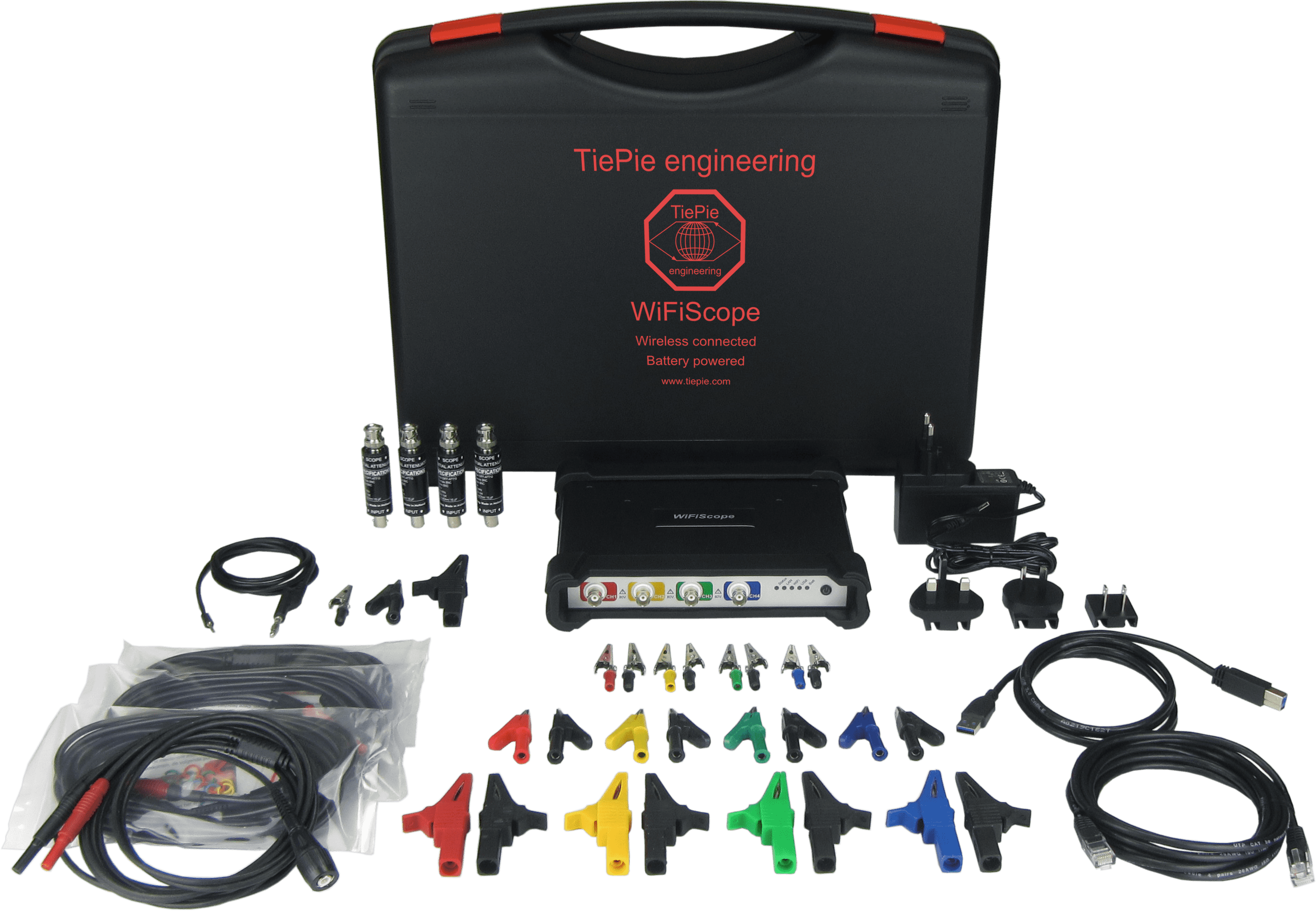
| Accessoires | 4 x Differential attenuator TP-DA10 external power cable for second USB port | ||||
| Software | Windows 7, 8, 10, via website | ||||
| Drivers | Windows 7, 8, 10, via website | ||||
| Manual | instrument manual and software user's manuals color printed on paper and digital, via website | ||||
| Total package weight | Approx. 3 kg | ||||
The Automotive Test Scope ATS5004D is delivered with:
| Cary case | Carry case BT341 |
|---|---|
| Instrument | Automotive Test Scope ATS5004D |
| Measure leads | 4 x Measure lead TP-C1812B, Differential BNC -> 4 mm banana plug |
| Differential attenuator | 4 x Differential attenuator TP-DA10 |
| Software | for Windows 7/8/10, via website |
| Drivers | for Windows 7/8/10, via website |
| Manuals | instrument manual and software user's manuals color printed and digital, via website |
Several downloads for the Automotive Test Scope ATS5004D are listed below, including Multi Channel oscilloscope software, drivers and manuals.
Driver & Software
| Description | Version | Remarks | Size | |
|---|---|---|---|---|
| USB driver | 8.1.9 | Windows 10, 32 and 64 bit | 3.80 MB | download |
| Multi Channel software | 1.43.4 | Windows 10, 32 and 64 bit, including PDF manual | 91.76 MB | download |
Manuals & Documents
| Description | Version | Remarks | Size | |
|---|---|---|---|---|
| Multi Channel software manual | 1.07 | English | 4.86 MB | download |
| Automotive Test Scope ATS5004D Instrument manual | 2.27 | English | 1.03 MB | download |
| Automotive Test Scope ATS5004D Datasheet | English | 2.41 MB | download |
Performing a SureConnect connection test
The connection test function of the Multi Channel oscilloscope software is briefly explained,with explanation how to do a connection test.Read whole article...
Performing a resistance measurement
The resistance measurement in the Multi Channel oscilloscope software is briefly explained.Read whole article...
Performing a power measurement
Engine power measurement (kW and hp) with accelerometer and lab scope, performed while driving a vehicle,without dyno or other test facilities.Read whole article...
Performing a relative compression test
The relative compression test in Multi Channel oscilloscope software is briefly explained, with instructions on how to perform arelative compression test with just a lab scope and current clamp.Read whole article...


Safe measuring using differential inputs
An automotive oscilloscope with differential inputs avoids damaging car electronics as result of a wrongconnection during measuring.Read whole article...

Comments are closed.